Throughout 2016 and 2017, detailed design works will take place along the onshore cable route. These works will involve some site investigation campaigns and we have provided more detail on what each campaign will involve below.
Some of the equipment involved is also shown at the bottom of this page.
Full information on these individual topics is available by clicking on each of the headings, below.
Archaeology evaluation and Trial Trenching
General overview
An Archaeological Trial Trenching campaign will investigate the full route of the onshore cable corridor, including the fields adjacent to the landfall location and the onshore Substation and Intermediate Electrical Compound sites.
These works are required to ensure any important archaeological sites are identified and protected in accordance with planning policy and the commitments in the Triton Knoll Development Consent Order.
Trial Trenching is a trench digging technique used to establish the presence, condition and date of any archaeological remains which may be present.
The process usually follows non-intrusive investigations, such as assessments of aerial photography, desk-based assessments and / or geophysical surveys. In the case of Triton Knoll, geophysical surveys supported by investigations of existing data have determined the location and number of trenches required
Latest Update
Work got underway on Monday, July 31, 2017. If you would like to know more about these investigations, please see our Q&A document which should answer most queries.
If you have any further questions or issues you’d like to raise, or would like to know more, please contact us either by phone on 0845 026 0562 or by email info@tritonknoll.co.uk .
[accordion clicktoclose=”true”]
[accordion-item title=”Process” state=closed]
Trial trenching work will be carried out by archaeologists at each location. The team will be made up of a Project Officer and two Project Archaeologists, who are supported and accompanied by an appropriately qualified machine driver.
A meeting with landowners will be arranged to determine the most appropriate means of access to the relevant land plots, in order to minimise crop loss and to cause the least amount of disturbance to normal farming practices. A record of condition will be made before any work starts.
Trenching
The campaign will involve the excavation of around 300 trenches of approximately 2m wide by 20-50m long, spread across various fields.
Teams will work on up to three different sections of the route, opening on average 3 x 20-50m trenches at any one time.
Each will be fully equipped with a survey grade Global Positioning System (GPS) to locate trenches accurately.
Trenches will be excavated using a tracked mechanical excavator fitted with a smooth edged, ditching bucket. Some excavations may be carried out by hand. Either a JCB 3CX or rubber tracked 6-8t excavator (depending on ground conditions) would be used to dig the trenches.
Once the archaeological horizon or natural horizon is encountered, machine excavation will stop.
Any archaeological features found will be surveyed and hand excavated, sufficient to identify the type of remains and their date. For many sites, a trial trench evaluation is sufficient to demonstrate no archaeological remains are present. The exposed soil will then be logged.
Any finds will be retained for later examination and soil samples may be taken to help identify a feature’s function, or to give information about the past surrounding landscape and environment. Soil data will also be recorded.
Once the work in the trench is complete it will be backfilled, replacing the strata in the reverse order to which it was excavated.
A full post record of condition will be undertaken to ensure appropriate reinstatement work has been completed to a satisfactory standard.
[/accordion-item]
[accordion-item title=”Plant and Work Equipment” state=closed]
Plant will include the following:
- A company welfare van with mess facilities including hand washing, microwave, hot water boiler and a fixed table will be provided.
- Additional vans and 4×4 vehicles may also be utilised, if ground conditions require their use.
- Spill kits will be included with the company vehicle for emergency use.
- Either a JCB 3CX or rubber tracked 6-8t excavator
- Equipment A Leica GS08 RTK NetRover GPS CAT Scan to locate trenches accurately
- Hand tools (e.g. trowels, shovels and picks.)
[/accordion-item]
[accordion-item title=”Indicative Sequences of Tasks” state=closed]
In general, the indicative sequence of tasks is as follows:
- Engage with landowners, tenant and agents to agree pre-entry information.
- On arriving at site make contact with the ESG Site Supervisor.
- Attend site specific induction prior to start of works.
- Undertake final confirmation of trial trench location and access arrangements.
- Ensure all emergency access points are clear and observe site speed limits at all times.
- Ensure all staff involved with the work undertake a pre job briefing and Point of Work Risk Assessment, to cover access and egress, onsite health & safety, dealing with risk and mitigation.
- Undertake final pre-work checks and monitoring
- Excavations take place, mechanically and by hand (all trenches to be protected by high-visibility fencing, which is checked daily and removed after work.)
- Findings recorded and stored.
- Reinstatement undertaken.
[/accordion-item]
[/accordion]
Geophysical Surveys (Geophys)
General Overview
Geophysical surveys (or ‘geophys’ for short) may use a number of different methods and sensing instruments to collect information about the physical properties of land so that features in the subsurface can be identified. Readings are collected in a systematic fashion over a site, often covering large areas quickly.
Instruments can be handheld, pushed on a cart or pulled across the ground. The type of equipment is selected depending on the target object and site conditions. The results of surveys can be used to reveal water table depths, unexploded ordnance, underground services such as drainage pipes, or archaeological remains. Large areas can be covered in a single day using portable equipment.
These surveys are non-intrusive in that the surface of the land is undisturbed. However, crops growing above a certain height may interfere with the operation of the equipment.
[accordion clicktoclose=”true”]
[accordion-item title=”Process” state=closed]
The area in question is surveyed in a grid pattern to build up a picture of below ground features. Vehicle access adjacent to the survey area is required.
[/accordion-item]
[accordion-item title=”Plant and Work Equipment” state=closed]
In general, equipment used on site would include:
- Hand held instruments
- Cart mounted instruments
[/accordion-item]
[accordion-item title=”Indicative Sequences of Tasks” state=closed]
In general, the indicative sequence of tasks is as follows:
- Engage with landowners, tenant and agents to agree pre-entry information.
- On arriving at site make contact with the Site Supervisor.
- Attend site specific induction.
- Confirm the location of the survey and agree access route and arrangements.
- Agree if additional equipment will be required. Keep all emergency access point clear and observe site speed limits.
- Provide all staff involved with the work a pre job briefing and Point of Work Risk Assessment. The pre job briefing will include:
- Access and egress requirements
- Permit to Work Requirements
- Potential hazard reporting
- Potential contaminated land risks
- Specific PPE requirements
- Potential slips, trips and falls
- Contact with other third parties
- Carry out survey over required area in accordance with the Contract Specification and Environmental Scientifics Group (ESG) Standard Operating Procedures.
[/accordion-item]
[/accordion]
Trial Excavations (Trial Pits)
General Overview
Trial pit or trial trench excavations are carried out in order to study or sample the composition or structure of the subsurface, such as for pre-construction assessments or for archaeological investigations. Compared with light-cable percussion drilling or window sampling, this method of work is relatively quick but results in a greater surface area for reinstatement.
Trial pits are usually carried out when the ground is able to stand temporarily unsupported. Temporary shoring can be employed, for example where there is water present in the excavation or where in-situ testing is required.
Prior to commencing survey works the test location is hand dug to 1.2m to check for any buried services or other hazards. Following this a mechanical excavator is usually appropriate for excavating trial pits or trenches. Hand tools may be employed where underground services are known to exist.
[accordion clicktoclose=”true”]
[accordion-item title=”Process” state=closed]
A ‘before’ record photograph will be taken of the area to be excavated. Areas will be ‘CAT’ scanned for services by trained personnel.
Trenches and pits are normally mechanically excavated, in which case vehicular access will be required. The type of machine will vary, and therefore so will the size of the blade used. The machining will be monitored by an archaeologist. Thin layers of soil will be stripped from ground level to slowly form a trench. Each stripped layer is examined in detail and if required, samples representing the strata encountered are recovered for further detailed analysis and laboratory testing.
Trial pits will be backfilled upon completion to make safe, replacing the strata in the reverse order to which it was excavated, to the best degree possible, thereby returning the site to the state in which it was found. Should it be necessary to leave a trench ‘open’ overnight, it will be fenced on all sides with netlon fencing and iron road pins, and fitted with adequate signage, unless otherwise specified.
[accordion-item title=”Plant and Work Equipment” state=closed]
In general, equipment used on site would include:
- Mechanical excavator
- Hand tools
- CAT scanner
- Spill Kits
- Netlon Fencing & Pins
- Sampling kits
[/accordion-item]
[accordion-item title=”Indicative Sequences of Tasks” state=closed]
In general, the indicative sequence of tasks is as follows:
- Engage with landowners, tenant and agents to agree pre-entry information.
- On arriving at site make contact with the Environmental Scientifics Group (ESG) Site Supervisor.
- Attend site specific induction.
- Confirm the location of the excavations and agree access route and arrangements.
- Agree if additional plant will be required. Keep all emergency access point clear and observe site speed limits.
- Provide all staff involved with the work a pre job briefing and Point of Work Risk Assessment. The pre job briefing will include:
- Access and egress requirements
- Permit to Work Requirements
- Potential hazard reporting
- Potential contaminated land risks
- Specific Personal Protective Equipment requirements
- Buried service precautions
- Potential slips, trips and falls
- Potential pollution and mitigation
- Contact with other third parties
- Check service plans, CAT scan location and confirm location is clear. Ensure Permit to Dig has been issued.
- Position excavator.
- Carry out excavation to required depth in accordance with the Contract Specification and ESG Standard Operating Procedures
- Reinstate to landowners satisfaction.
[/accordion-item]
[/accordion]
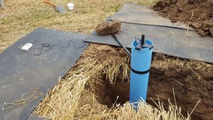
Cone Penetration Testing (CPT)
General Overview
Site investigation using the cable percussive boring technique may be required in close proximity to where the cable route crosses obstacles such as main drains, river and roads and trenchless crossings are required.
The cone penetration test (CPT) is a common in situ testing method used to determine the geotechnical engineering properties of soils and assessing subsurface stratigraphy. The test is also called, Dutch Cone test. Due to its simplicity and efficiency, the cone penetration test is one of the most commonly accepted and used in-situ testing methods in geotechnical investigation worldwide.
[accordion clicktoclose=”true”]
[accordion-item title=”Process” state=closed]
Prior to commencing survey the test location is hand dug to 1.2m to check for any buried services or other hazards. Following this the test method consists of pushing an instrumented cone, with the tip facing down, into the ground at a controlled rate (controlled between 1.5 -2.5 cm/s accepted). The resolution of the CPT in delineating stratigraphic layers is related to the size of the cone tip, with typical cone tips having a cross-sectional area of either 10 or 15 cm², corresponding to diameters of 3.6 and 4.4 cm.
[/accordion-item]
[accordion-item title=”Plant and Work Equipment” state=closed]
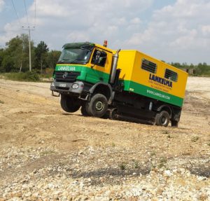
In general, equipment used on site would be limited to CPT Truck/Crawler.
[/accordion-item]
[accordion-item title=”Indicative Sequence of Tasks” state=closed]
In general, the indicative sequence of tasks is as follows:
- Engage with landowners, tenant and agents to agree pre-entry information.
- On arriving at site make contact with the ESG Site Supervisor
- Attend site specific induction.
- Confirm the location of the borehole and agree access route and arrangements.
- Agree if additional plant will be required to assist the rig move. Keep all emergency access point clear and observe site speed limits.
- Provide all staff involved with the work a pre job briefing and Point of Work Risk Assessment. The pre job briefing will include:
- Access and egress requirements
- Permit to Work Requirements
- Potential hazard reporting
- Potential contaminated land risks
- Specific PPE requirements
- Buried service precautions
- Potential slips, trips and falls
- Potential pollution and mitigation
- Contact with other third parties
- Check service plans, CAT and Genny scan location and confirm location is clear. Ensure Permit to Dig has been issued.
- Position CPT rig over pit
- Carry out CPT test to specified depth in accordance with the Contract Specification and ESG Standard Operating Procedures
- Remove CPT rods
- Reinstate to landowners satisfaction.
[/accordion-item]
[/accordion]
Cable Percussive Boring (Bore Holes)
General Overview
Site investigation use the cable percussive boring technique may be required in close proximity to where the cable route crosses obstacles such as main drains, river and roads and trenchless crossings are required.
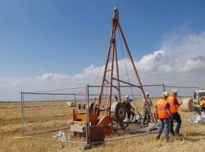
Light-cable percussion drilling uses a mobile rig with a winch of between one to two tonne capacity driven by a diesel engine and a tripod derrick of about 7m height. The derrick folds down so that the rig can be towed by a four-wheel drive vehicle. In areas where there is restricted headroom or access limitations a demountable or low-headroom drilling rig can be used. This rig is brought to site in sections on a trailer and the equipment is re-assembled on site. In areas where ground conditions are soft or wet, a tracked vehicle may be utilised to reduce ground pressure and impacts on soils.
[accordion clicktoclose=”true”]
[accordion-item title=”Process” state=closed]
Prior to commencing survey works the test location is hand dug to 1.2m to check for any buried services or other hazards. Following this the borehole is formed using either a ‘clay cutter’ for cohesive soils or a ‘shell’ (or bailer) for non-cohesive materials. A chiselling tool can be used to penetrate very hard ground conditions or obstructions. The sides of the borehole are supported using steel casing which is lowered into the ground as the boring proceeds. If the exploratory hole is formed in sands or gravels, particularly within the saturated zone below the water table, the steel casing will be pushed into position to support the borehole sides to allow any insitu testing to be carried out and the material to be removed using the shell.
The material recovered from the borehole is generally sufficiently representative to determine the depth and description of the geological strata. Disturbed samples may be collected from both the clay cutter and the shell. Undisturbed samples may be recovered from any cohesive strata or from weak chalk by driving a hollow tube (100mm open tube sampler) into the ground and withdrawing the resultant core for examination and laboratory analysis. Thin-walled piston samples are used for recovering undisturbed samples of soft normally consolidated soils.
[/accordion-item]
[accordion-item title=”Plant and Work Equipment” state=closed]
In general, equipment used on site would include:
- Cable percussion rig (Dando 2000 or 3000)
- Casings
- Drilling ancillaries e.g. stubbers, chisels, sinker bars
- CAT and Genny
- Full body harness and lanyards
- 4×4 Vehicle
- Spill Kits
- Ground Guards if required
- Heras Fencing
- Water bowser
- Plant trailer
- Hagglund Hybrid Rig (tracked vehicle)
[/accordion-item]
[accordion-item title=”Indicative Sequence of Tasks” state=closed]
In general, the indicative sequence of tasks is as follows:
- Engage with landowners, tenant and agents to agree pre-entry information.
- On arriving at site make contact with the ESG Site Supervisor
- Attend site specific induction.
- Confirm the location of the borehole and agree access route and arrangements.
- Provide all staff involved with the work a pre job briefing and Point of Work Risk Assessment. The pre job briefing will include:
- Access and egress requirements
- Permit to Work Requirements
- Potential hazard reporting
- Potential contaminated land risks
- Specific PPE requirements
- Buried service precautions
- Potential slips, trips and falls
- Potential pollution and mitigation
- Contact with other third parties
- Erect fencing around borehole location.
- Check service plans, Refer to recognition of safe digging procedures in accordance
- Obtain ‘Permit to Dig’ from the client.
- Excavate inspection pit
- Using vehicle, position rig over inspection pit.
- Unload equipment from rig and erect rig.
- Install lead length of casing and casing head in inspection pit.
- Insert boring tool inside casing. Attach to casing head with surging pin.
- Activate winch and lift tool and casing combination and enter it into the ground vertically.
- Remove surging pin and release winch brake to drop tool to base of the borehole.
- Activate the winch so tools penetrate the ground.
- Remove tool from borehole and clean arisings.
- Bag and contain arisings.
- Reinsert tool and repeat until sample/test depth is reached.
- At test/sample depth, carry out SPT or UT100.
- Take intermediate bulk (bag), disturbed (tub) or water (bottle) sample as instructed or contamination samples.
- Proceed to borehole termination depth.
- Install instrument, backfill with arisings or grout as specified.
- Remove cable tool casing in lengths using winch.
- Lower rig.
- Load equipment onto rig and secure with ratchet straps.
- Before moving off position, confirm borehole is correctly backfilled so no depression can occur.
- Remove all spoilage, waste and fencing and reinstate to landowners satisfaction.
[/accordion-item]
[/accordion]